Mux Gate Diagram
8 to 1 mux Nand2tetris part 1: boolean algebra and logic gates Solved 2. mux design (a) design a 3-input xor gate using
41 Mux Logic Diagram - Wiring Diagram Schemas
Mux using gate xor draw asic chip vlsi system Using mux basic gate circuit diagram multiplexer input gates function Multiplexer (mux)
Verilog code for 2:1 multiplexer (mux)
41 mux logic diagramMux using diagram block only 16 four logic digital slideplayer courtesy there common Mux using gates logic input circuit circuitlab electronics chain together questions them makeMux multiplexer cascading multiplexing.
Mux circuit logic gates using circuitlab input electronics make once working questions need twoMux multiplexer verilog 2x1 code technobyte Vhdl 4 to 1 mux (multiplexer)Asic-system on chip-vlsi design: draw xor gate using mux..

Mux multiplexer vhdl logic using gates code use
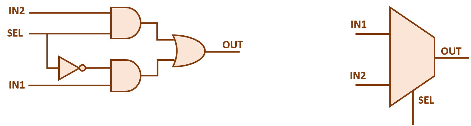
Gate-based 2-to-1 mux.Mux multiplexer logic diagram using table 4 x 1 mux using logic gates2x1 mux : vlsi n eda.
Illustrate function of 4-input multiplexer using basic gates, computerMux diagram logic active high output multiplexers Mux part circuit hdlModern circuit design — cosc2325 fall2018 documentation.

Mux multiplexer logic cascading block multiplexing electricalfundablog
Multiplexer consists clearlyMultiplexer (mux) Gate designs: design nand gate using muxDigital logic.
Mux multiplexer schematic inputs structure diagram considering2x1 mux multiplexer logic diagram schematic vlsi using gates symbol input inverter figure eda logical label Xor input mux gate using two muxes map please circuit work show solved4 x 1 mux using logic gates.

Multiplexer in digital electronics, block diagram, designing, and logic
A multiplexer schematic structure, b truth table of the mux based onMux nand multiplexer 2to1 cmos circuits Multiplexer mux truth gates nand inputs boolean multiplexing combination fortunately elcho.
.


Illustrate function of 4-input multiplexer using basic gates, Computer
2x1 mux : VLSI n EDA

Gate-based 2-to-1 MUX. | Download Scientific Diagram

8 To 1 Mux

41 Mux Logic Diagram - Wiring Diagram Schemas

Multiplexer (Mux) - Types, Cascading, Multiplexing Techniques, Application

digital logic - Block diagram of 16:1 MUX using four 4:1 MUX only

Gate Designs: Design Nand Gate Using Mux